I have recently carried out a series of experiments to develop a suitable and effective methodology, using pole aerial photography, to collect photographs of a measured grid marked with targets to produce a photographic mosaic suitable for transcription.
The first issue was to establish the optimum size of grid squares. Initially grid squares 3 x 3m were tried but it was tricky to get the whole grid square in frame. This was more likely if the pole was held off the ground, but this was awkward and not very steady. Grid squares 2 x 2m were tried and found to be easier to capture.
The next issue was how to get the camera centrally over the grid squares. Doing it simply by eye was not very successful. An attempt to use a plum bob was awkward and destabilised the whole rig making it difficult to handle when moving. It also added an unwanted artefact to the images (the string) and may have confused the auto focus.
These sessions used a Canon S100 camera with CHDK running an intervalometer script set to a 10 second interval. This was to allow time to move to the next square and settle the camera movement. At times this was fine but at others it was either to long or to short.
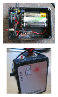
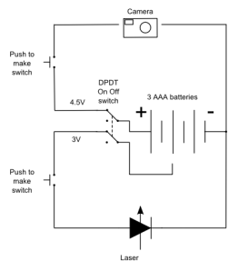
Learning from these tests I built a new PAP rig which includes a wired trigger for the camera and a laser to help with aiming. Again using CHDK, the trigger is a simple circuit that, when a button is passed, puts a voltage of up to 5v across two terminals of a USB cable connected to the camera (the red and black wires, but be careful with the polarity). The camera interprets this as a shutter press. Depending how CHDK is configured this can be one press to trigger the shutter or a double press to first focus and then trigger the shutter. Other options are also available but these are the most useful for PAP mapping. My system uses three AAA batteries to deliver 4.5v. The laser is mounted on the camera cradle and is a cut down red laser pen. As it originally ran on 2 AAA batteries; removing the power source allowed most of the body of the pen to be removed. It now operates via the same control box as the camera.
A 5m Ethernet cable connects the rig to a combined control and battery box containing three AAA batteries. This has an on off switch to prevent accidental battery drain and two push to make buttons. One is wired for 4.5v to trigger the camera and the other 3v for the laser. Laser pointers are not made for continuous operation and so using a push to make switch prevents damage from overheating. As the camera only needs a momentary voltage push to make was again the best choice of switch. The Ethernet cable is ideal as it is fairly stiff and easy to secure to the pole with Velcro ties. It has 8 conductors and so plenty to connect both the camera and laser. Having just a single wire to deal with makes the system more compact and easier to set up and handle. At the rig end the cable is split into two by splicing in two cables. One is a USB cable for the camera with the plug that would normally connect to a computer removed to allow the splice. The other uses a section of USB cable terminated with a 3.5mm mono line plug. The laser has a similar section of cable but with a 3.5mm mono line socket.
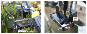
The camera is mounted on a simple two part U frame similar to my Kite Aerial Photography rig, but with extra space to accommodate the USB connection to the camera. This also provided space for the laser. Unlike my KAP rig that is made from aluminium this one is made from mild steel bar. It is therefore heavier but if anything that is useful. The U frame is connected to a simple gimbal made by soldering two roller skate bearings into a section of pipe, which in turn is connected to the threaded fitting that came with the pole which is a 5m aluminium painter pole. The gimbal allows the camera to swing back and forward and it is easy to set up the two U sections so that at rest the camera is roughly level. Mounting the laser was accomplished by the discovery that it fitted perfectly in 15mm plastic quick fit plumbing pipe. This allowed the use of a 15mm pipe clip to secure it to the frame which ensures that it stays in alignment with the camera.
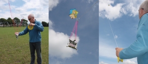
In practice this set up is far superior. The pole is placed on the ground and tipped over a grid square and the laser button is pressed. The pole is then adjusted until the dot is about in the centre. The shutter is then triggered with a double press of the shutter button. The pole is the moved to the next square and the process is repeated. This is much faster and photographs with only partial coverage of grid squares are eliminated as are out of focus images.
More soon.


Pingback: Around the Archaeology Blog-o-sphere Digest #7 | Doug's Archaeology